Lighting System with Communication and Synchronization Capabilities
Everything started with an invitation from my technical club, WAK-Lab e.V., to a local festival called “Everland,” organized by Neue Welten e.V. They were looking for ideas to illuminate the forest. We divided the tasks within the club, and I was assigned to create tree lighting. Since there were only three weeks left until the festival, I needed a very quick and cost-effective solution. This led to the creation of the first prototype of my lighting system.
This prototype surprisingly worked and didn’t catch fire. The festival visitors were very enthusiastic about the look of the illuminated trees, and I received a lot of positive feedback.
For the following year, I wanted a challenge and decided to equip the system with Wi-Fi to make the trees light up in sync.
Description
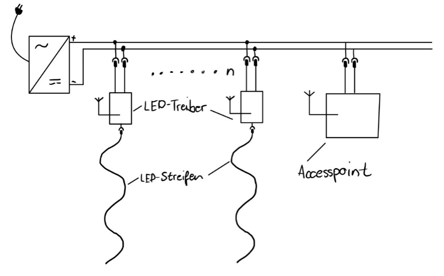
The project essentially consists of LED drivers that control the LEDs and provide the necessary supply voltage. To get the electrical power to the LED drivers, they are connected to a long cable via power taps. At the beginning of the cable, there is a very powerful 24V power supply.
A Wi-Fi router (access point) is also connected to the cable, providing a network that the LED drivers can log into and wait for their data. This data is sent to the LED drivers in the form of UDP packets over the Wi-Fi network. The source of the UDP packets is not fixed, so any Wi-Fi-enabled device can control the LED drivers. This makes the system very open and decentralized.
Construction
LED Driver Construction
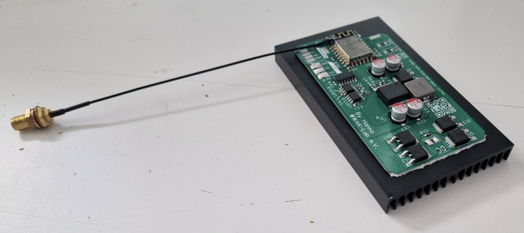
The LED driver, as the name suggests, is responsible for controlling the LEDs. These LEDs are digital, addressable LEDs with the designation WS2813. To control these, I had to select a microcontroller with Wi-Fi capability. I chose the ESP8266 from Espressif. However, since this microcontroller only tolerates 3.3V levels and the LEDs require 5V data levels and 12V supply voltage, while the board is powered by 24V, I needed some electronics to make everything work together. I designed the circuit boards using the free layout program DipTrace and ordered them from a well-known Chinese PCB manufacturer.
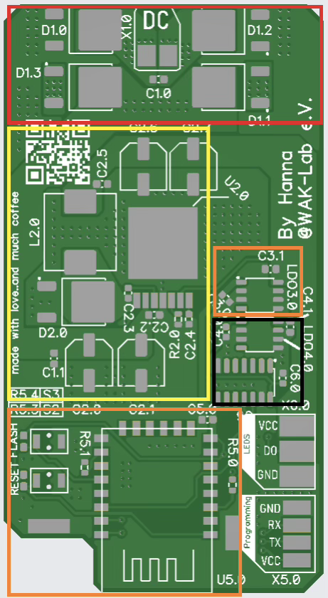
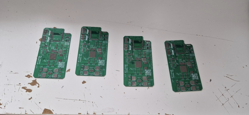
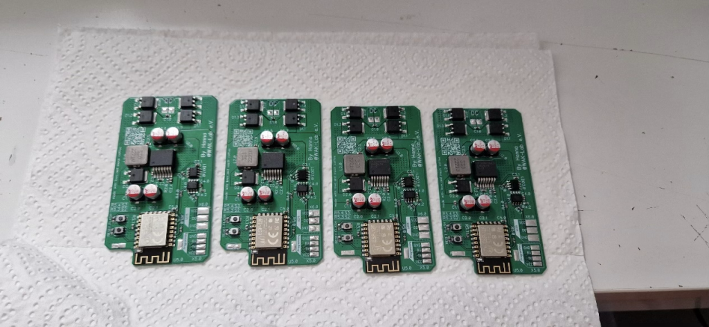
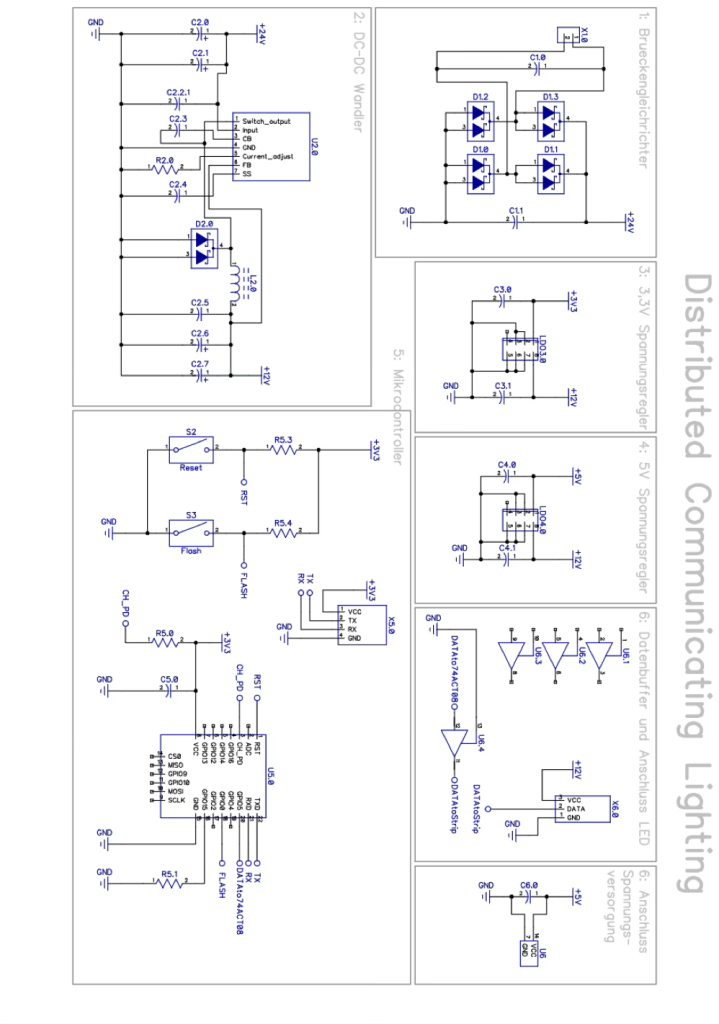
The image shows the different areas of my PCB for the LED driver:
- Red: Connection of the supply voltage, including four diodes for reverse polarity protection
- Yellow: DC-DC converter to step down from 24V to 12V
- Orange: ESP8266 and 3.3V voltage regulator
- Black: Data buffer to raise the data level from 3.3V to 5V and a 5V voltage regulator
The PCB went through several revisions, mainly due to heat issues and the selection of the level shifter for the data. The heat issues were that the diodes in the red area and the DC-DC converter would unsolder themselves after a few minutes under full load.
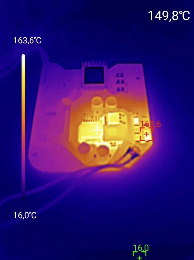
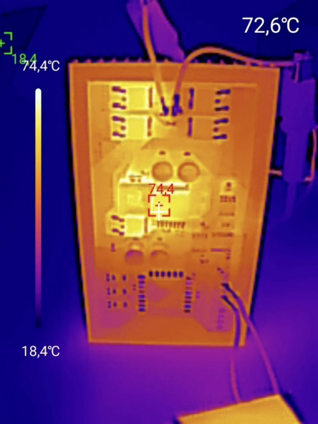
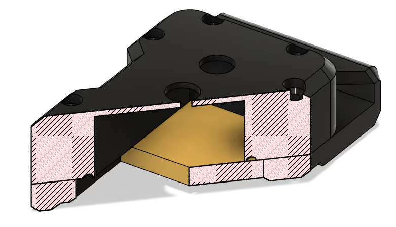
Since this functionality, while amusing, led to a failure, I decided to cool the PCB using a large heat sink. With some improvements to the heat transfer from the components to the back of the PCB, where the heat sink is attached with thermally conductive tape, the components stayed cool and secure.
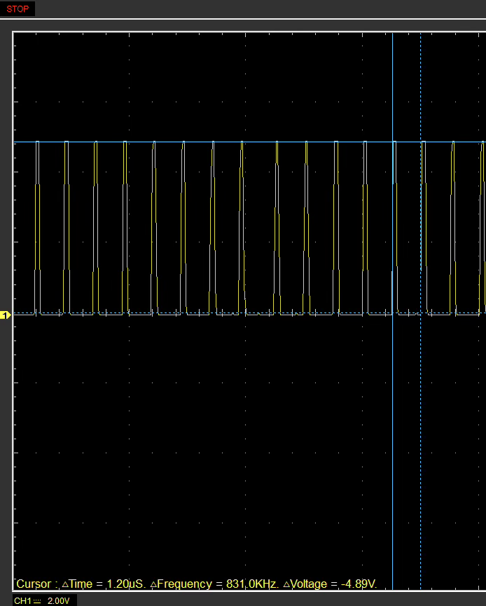
As mentioned, the level shifter was also a problem; it took three attempts to get it working. In the end, a CMOS data buffer with TTL-compatible inputs proved suitable for the job.
When testing the CMOS data buffer, I measured a HIGH level of 4.89V. The edges looked clean enough, and there were no issues with color reproduction.
Another challenge was soldering the PCBs, as they are fully equipped with SMD components. Therefore, I ordered the PCBs with a solder stencil and used solder paste. For the actual soldering process, I used a small hotplate that automatically regulates to about 220°C. After a few failed attempts, the soldering worked smoothly.
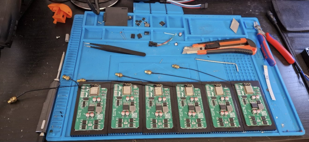
To ensure good Wi-Fi reception for the LED drivers, I decided to replace the PCB trace antennas on the ESP with a proper rod antenna. To do this, I cut the traces and soldered an antenna cable.
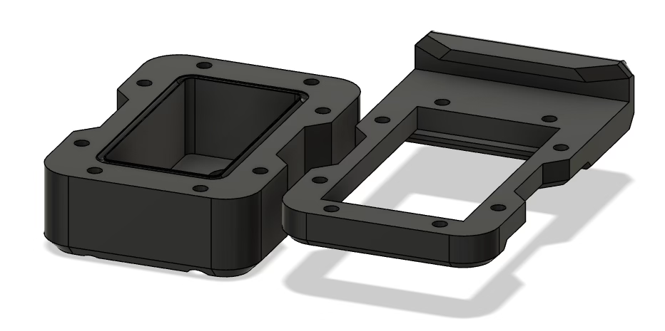
To protect the PCBs from environmental influences in the forest, I designed a housing using the free CAD program Fusion360, which I then printed with my 3D printer. This housing went through several development stages with small improvements each time, so in the end, I had a fairly tight housing in which my LED drivers fit. I needed 12 of these, so the printer ran for several hours without stopping.
Power Tap Construction
To allow the LED drivers to be connected to the power cable at any point, I developed a special power tap that uses the principle of insulation displacement technology, as used, for example, in AS-Interface. In insulation displacement technology, an electrical connection is made by penetrating the insulation of an electrical conductor.
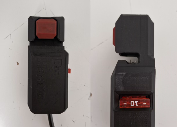
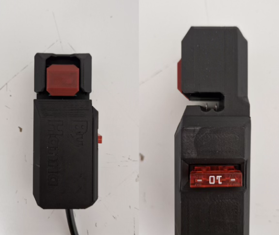
Since I had to use a 4mm² speaker cable for power distribution for cost reasons, I needed a penetration method that would damage the cable insulation as little as possible. This led me to the idea of using sewing needles. In the first prototypes, I connected the pins to the LED driver’s connection cable via screw terminals. However, this was less stable than expected. So I started experimenting with soldering the needles onto a PCB. After trying several soldering options, two solder points per needle proved sufficient. To prevent everything from burning immediately in case of a defect in the LED driver, I also equipped the power taps with 10-ampere automotive fuses.
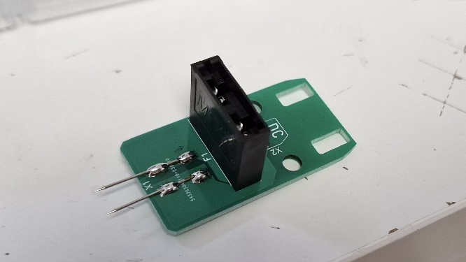
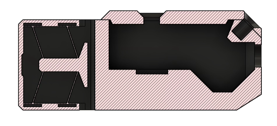
I also designed this PCB using the DipTrace layout program. Of course, the power tap also needed a housing. The requirements for this housing in terms of tightness were not as high. Nevertheless, I had to find a solution to securely hold the needles in the cable. Since the system was to be hung in a tree, the connection also had to be possible with one hand. Cable ties were therefore not an option. I decided to try something challenging and construct a clamp based on the principle of a compliant system. Compliant systems are characterized by the fact that movements are enabled not by classic joints but by deliberately flexible weak points.
So I studied compliant systems and tried to build a theoretical model using programs and online university courses, and then construct a 3D-printable model based on that. I quickly realized that you need to have studied this. So I just started constructing and, after a lot of trial and error, finally came up with a working mechanism.
Power Supply Construction
Without the power supply, nothing works. That’s why I paid particular attention to proper dimensioning in this part of the project. Since the LED strips require 12V and the power distribution cable lengths are so long that significant voltage drops are expected, I decided to distribute at 24V. Since the LED drivers work up to a voltage of about 14V, this left a 10V buffer for voltage drops. For cost reasons, I had to make do with 2x4mm² speaker cables for power distribution.
The power supply must be able to provide 24V at the corresponding current levels to operate as many LEDs as possible. Therefore, I opted for a Siemens industrial power supply with 1000W output. This should, at least theoretically, be sufficient for about 3900 LEDs.
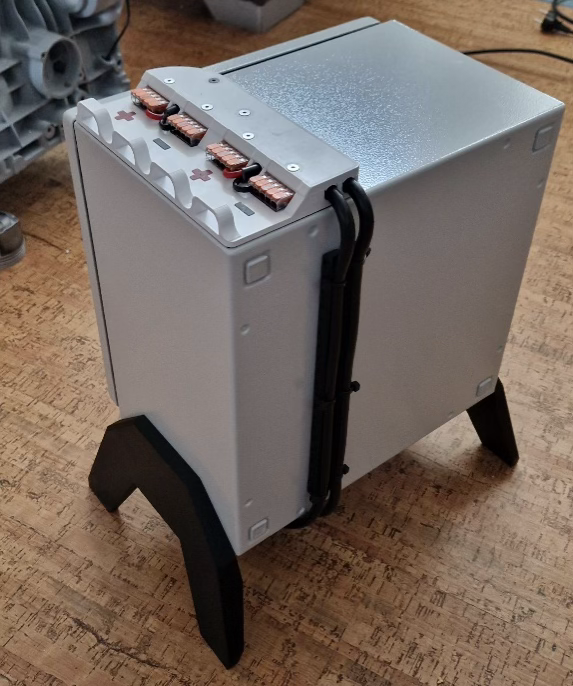
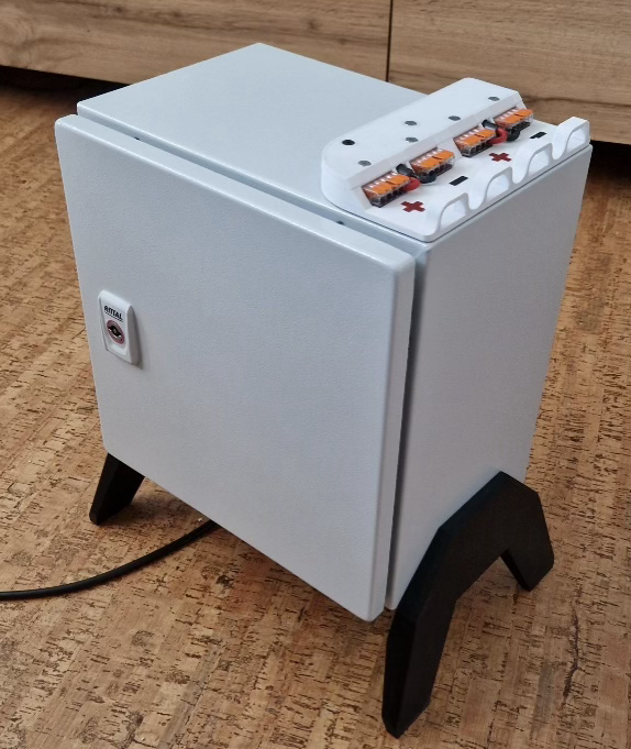
To protect the power supply from environmental influences in the forest, I selected a switchgear cabinet based on the power loss of the power supply. I then wired the switchgear cabinet according to DIN 61439 to prevent it from catching fire.
To connect the distribution line without opening the switchgear cabinet, I designed and 3D-printed a Wago terminal block holder.
Programming
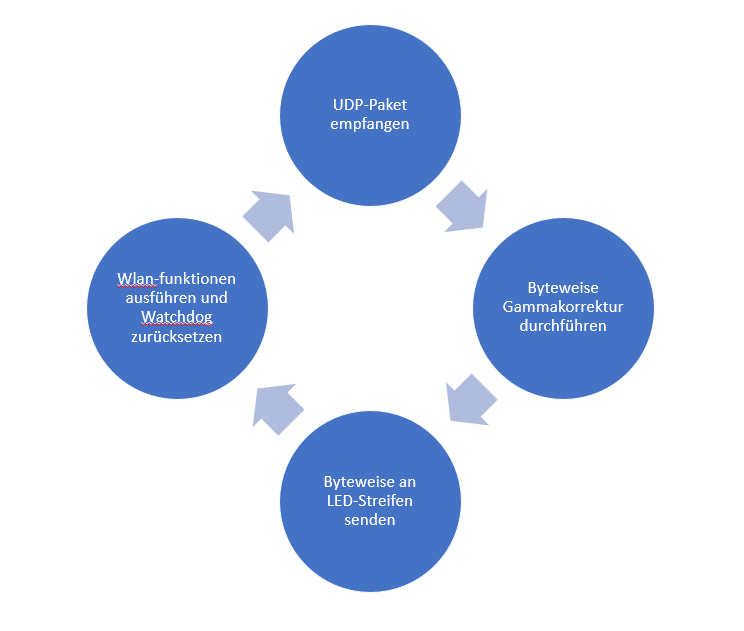
The ESP8266 microcontroller in the LED driver, of course, needed to be programmed to receive UDP packets and send the data accordingly to the LEDs.
I wrote the program using the Arduino IDE, and it consists of both “Arduino” code and C code.
The data bus through which the LEDs receive their data is not a standard but is very similar to the SPI bus. Since the ESP8266 does not have an SPI port, I had to solve this via software.
Bit-banging is often used in the Arduino world to emulate bus ports. Therefore, there was already a template for me in the NeoPixel library that contains the ESP-specific C code, which allowed the digital outputs of the ESP to be turned on and off in the nanosecond range. I could have simply used the NeoPixel library for the project. However, it turned out to be too slow, so I was forced to use the library as a reference and write my own, faster code.
It took many hours and a lot of head-scratching to get the code to work. There were problems with stability, speed, data output, and not least with the Wi-Fi connection. As soon as one problem was solved, the next one appeared. In the end, I managed to make the code stable enough for the LED drivers to function without crashing.
To test and operate the system, I also needed a source for UDP packets. I decided to write a small Python program on my laptop that sends UDP packets to the LED drivers. This worked surprisingly well without major problems. At least until I provided a graphical interface to make the system a bit more comfortable to operate. Since the focus was not on operating the system via laptop, I then concentrated on other problem areas of the project.
Summary
Since I did this project completely on my own, there were many challenges, whether in PCB design, construction, soldering, or programming. But precisely because I had to find solutions to all the problems myself, I dealt very intensively with the various topics and was able to learn a lot.
I got the PAUL eTECH Talents Award with this project, which is
The system was successfully used at the Everland Festival 2023 and greatly impressed the visitors. For future festivals, I want to expand the system further and add various control options. For example, I am currently working on a keyboard whose electronics I have replaced with my own, which will then make individual trees light up via keypresses, like a kind of light organ. Other ideas include a theremin and capacitive sensors on the trees.
I applied to the PAUL eTech Talents Award with this project and was awarded the second place, which is also nice 🙂
About Me
Hanna Lieding
Software/Electronics Engineer
Hello, I’m Hanni, I like to mess around with electronics, cars, drones, 3D-printers, code and broken things.
Leave a Reply