
Optimising a car perfume with Finite Element Method Analysis
Okay, I admit it, the title is a little catchy. But it describes this project pretty well.
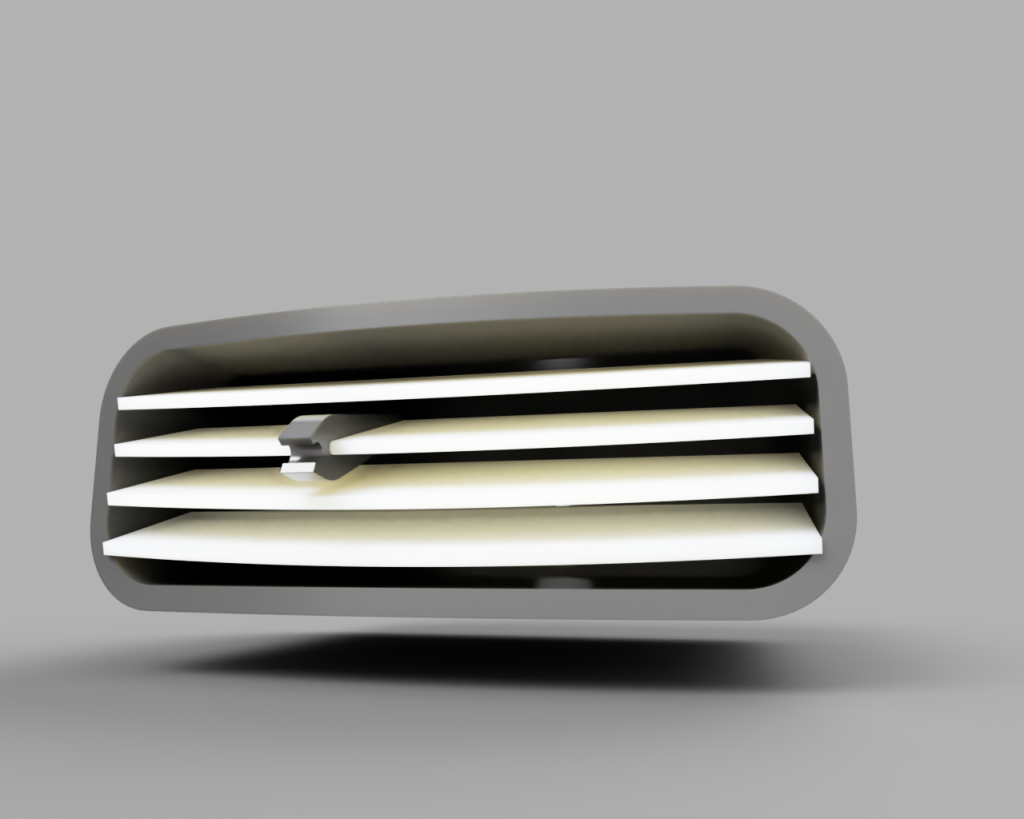
I got a car perfume and it did not fit into the vents of my car, so I designed a replacement for it’s little holder clip thingy. And of course 3D-printed it with PETG filament. And the fit was perfect… until the next very hot day. PETG filament has a heat deflection temperature (the temperature where it gets easier to deform) of a little over 60°C. You know what also gets to about 60°C? The inside of a car on a hot summer day^^
So the next logical thing was to print it with a filament better suited for high temperatures, I chose ASA because of the relatively easy handling and good printing properties:
– Not very Hygroscopic (in comparison to other engineering materials)
– heat deflection temperature of around 90°C
– UV resistance
This worked extremely well. This was around the time when I founded my company so I decided to sell this clip to people that maybe need it. And oh boy, those were many. Seemed like I found a niche market, the sells climbed, I struggled a little bit to keep up with the demand. After a few hundred sold, I noticed some (not many) complaints about the parts deforming on hot summer days. I tested the parts again in my oven and yes, they deform when under constant stress and heated to 70°C. I stopped selling them, not only for this reason, I was also a little overworked, but I also did not want to ship parts that can deform.
This was a few months back and now I decided to address this topic once more to design the best car perfume clip as possible.
So what could be the issue that causes the parts to deform? I have some theories on that.
ASA (Acrylonitrile styrene acrylate) is a thermoplastic, which means it gets weaker when heated, that’s why it can be printed. The transition from hard to soft happens gradually, so it will be weaker at higher temperatures. That in combination with the constant stress (that is introduced by the clamping) it deforms.
So there are three factors that influence the failure, the heat, the material and the stress. Which means I need to get a material that can handle heat even better. I also need to better manage the stresses within the part, maybe distribute it better to not overstress any regions.
The material choice
I wanted to mess around with PA filaments for a long time now, they also seem to be in the same requirement ballpark of mechanical properties that are suitable for this application.
Comparing mechanical properties of materials from datasheets without having *any* real knowledge about material science was.. frustrating. But also very interesting. Maybe it would have been easier if I listened to my teacher in material science classes, instead of doing something that interested me more at this moment. Maybe that would have been easier if I considered getting tested for ADHD earlier.
There are two commonly used PA-polymers in 3D-printing, PA6 and PA12. Both of them come reinforced with carbon-fiber or glass-fiber. From the information I could gather, PA6 is cheaper and more rigid than PA12, but is very hygroscopic. PA12 is more flexible but also more expensive. Both can be annealed, PA6 looses more strength when not annealed.
With being hygroscopic, PA6 is not only required to be dried before printing, it’s also much weaker when wet.
I decided to buy a roll of PA6-GF (glass fiber reinforced) and a filament dryer. The cost of PA12 is so high that I doubt I would make a profit selling the parts made of it. PA6 is less flexible, so I have to see if it will be a problem. I will also have to anneal it, maybe it is possible to anneal it right after printing with the heated bed of the printer and some custom G-code.
Part geometry
Now that I have made a material choice, I need to redesign the part to optimize the crap out of it. I designed the ASA-part mostly by trial and error and concentrated more on avoiding support structures to save time when printing a batch. That did’t work very well, resulting in parts that looked ugly.
I am not sure if I want to try to avoid support structures again or just make them as easy to remove as possible. That’s a problem for future Hanni.
The problem for current Hanni is to design the clamping mechanism.
There are many ways to design a clamping mechanism, I figured three different approaches.
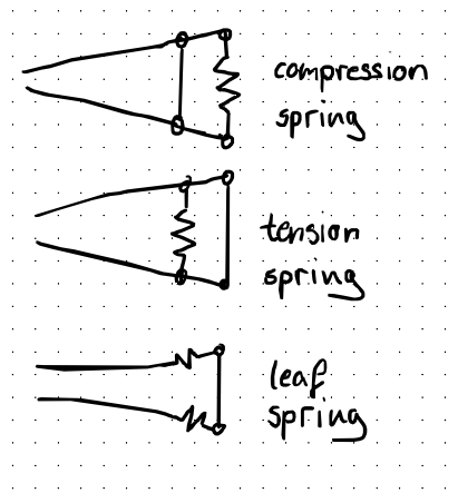
The springs in the image won’t be real metal springs, they just represent the direction in which the material needs to flex, creating a rigid-body-spring. Which is basically a compliant mechanism.
A compliant mechanism only works as long as the material is only deformed within it’s elastic domain. This can be achieved by using a very flexible material or by distributing the deformation applied by the stress on the material.
As I cannot make the part significantly larger, the strain needs to be distributed over the arms, making the leaf spring approach best suitable.
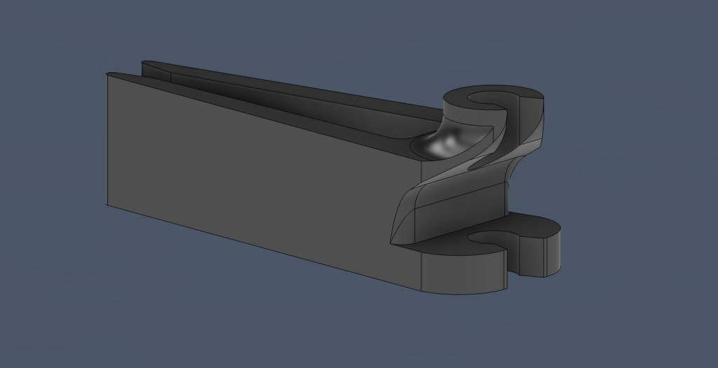
The car perfume came with a clip, in order to see what approach the manufacturer took, I need to see how and where it deforms under stress. So I completely measured the part and modeled it in CAD.
I pondered about getting into the whole FEM-Analysis stuff for a while now, but as I’ve always used Autodesk Fusion for designing things, I was always scared away by the huge paywall to access the FEM Features of Fusion. But for this project I wanted to get into it and paid 1.500€ for one year access to the fea- absolutely not. I won’t pay this kind of money for being able to run Simulations on a 10€ part. The prices for the commercial version of Fusion are too high already. So I went on looking for alternatives and found FreeCAD, I already knew about it but I heard that it is pretty complicated compared to Fusion. But in the meantime they improved it quite a bit, I’ll probably try using it and see if I can get away from Fusion payments in the future. Anyways, FreeCAD also comes with a preinstalled FEM-workspace to easily perform different types of FEM-analyses, including static mechanical analysis.
To perfom a static analysis in FreeCAD I watched a tutorial and got to it.
original clip with fixed and force constraints
Next step is Meshing.. and material selectio- oh… What material is the original clip made of? I hear the silent crack of the can of worms I am opening right now.
See, I don’t think the specific polymer of the original part has any real effect on the behavior of the part, as I look at it in a vacuum, so without any interaction to other things and only relative to itself. The specific amount of deformation from a given force does not matter at all. But the can of worms is open now. And I am very bad at ignoring things. But this whole little side project will be covered in a separate post, to keep it clean y’know.
Sooooo I chose PP-Generic as the FEM Material.
The analysis shows that most of the displacement is happening in the arms, which suggests that those are meant to be the spring.
So the manufacturer of the original clip also chose the leaf spring approach, nice. To the drawing board!
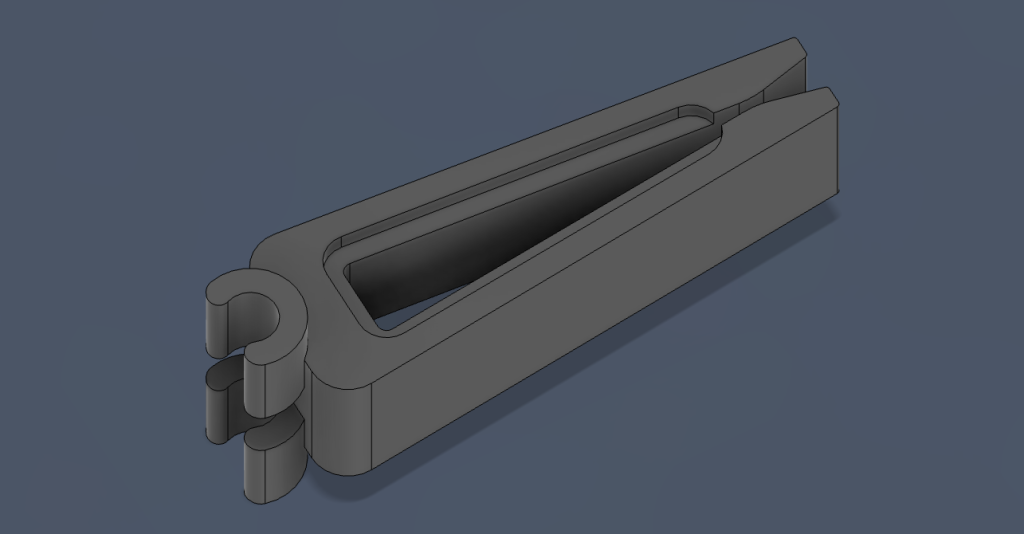
To get a feeling for the behavior of the part, I started out by designing the first draft by instinct. relatively thick base arms that get linearly thinner by length.
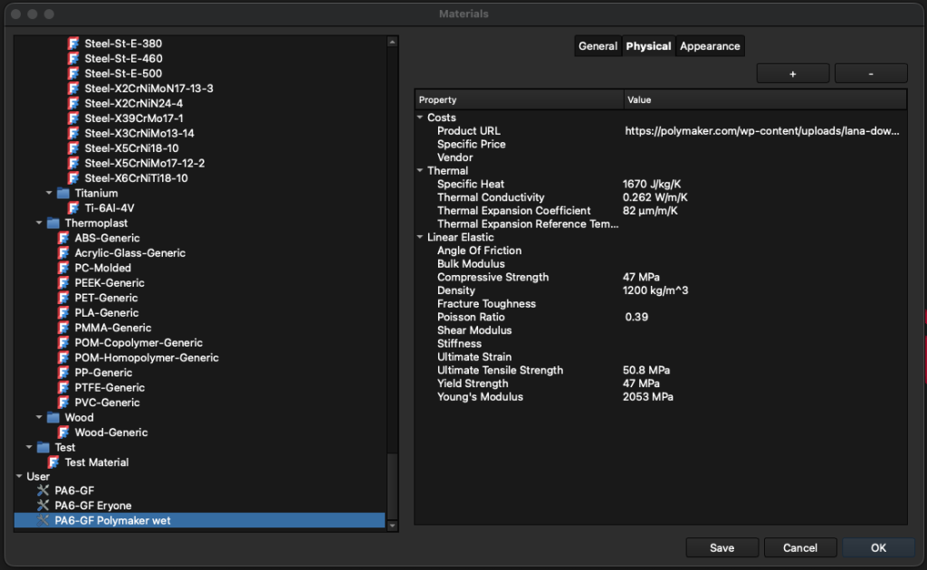
Now let’s throw it into FreeCAD and run the same analysis as on the original part, but this time I have to select a new material. In the materials selection is a PA6-Generic material. PA6-Generic is PA6 without any reinforcement, so the analysis won’t be accurate. The mechanical properties of the PA6-Generic also do not consider the production process of the part that will be tested, which is a huge factor when designing 3D-printed parts as they are inherently weaker and heavily dependent on the print conditions. Luckily the manufacturer of the filament that I want to use for the part provides a datasheet with some mechanical properties of printed parts.
But unfortunately the datasheet is for the PA6-CF, so the carbon fiber reinforced Nylon and Eryone just uses it for the PA6-GF as well. Another bummer is that there is no statement about post processing and moisture conditions of the tested parts. That doesn’t sound very important, but for PA6 it very much is. The mechanical properties can vary pretty dramatically with annealing and moisture. I can recommend this Video to learn more about this.
That means those values are not useful for me. I could just take values from a different manufacturer, but then I cannot be sure that those will be the same for my filament. But that’s the best option I have, so off we go.
There are not that many manufacturers for PA6-GF and many of them, like Eryone, don’t state annealing or moisture in their datasheets.
I found a datasheet for Polymaker PA6-GF that looks promising, they state annealing and moisture conditions, nice. But somehow the datasheet looks familiar…

“Yeah, copy my datasheet, but don’t make it too obvious” LOL
Anyway. I will work with the values of the Polymaker datasheet for now.
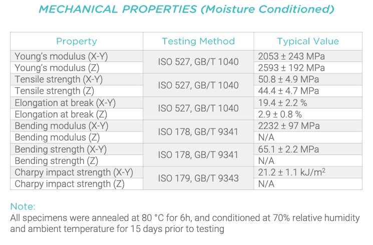
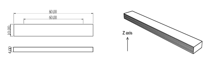
The datasheet provides measurements for dry and moisture conditioned material. The inside of a car will be moist, so the moisture conditioned values will be more accurate.
I will use the values in X-Y direction, so co-linear to the layers. Notice how the tensile strength is lower in Z direction. This is because the bond between individual layers of a 3D-printed part is the weakest throughout the part. I will design this part to have the highest loads in X-Y direction, so I will use those values.
Unfortunately the datasheet does not provide a measurement for the Yield Strength, which would be the most important value. It describes the strength of the part before the Yield-point, so before plastic deformation occurs. The Yield Strength of the generic PA6 material is about 5MPa lower than the Ultimate Strength, which is about 7%, so 47MPa seems like a reasonable approximation of the Yield Strength of PA6-GF. My reasoning is that the reinforcement makes the material more brittle, which means there will be less plastic deformation before breaking, which means that the Yield-strength to Ultimate-strength ratio will more likely be higher, which means that the real Yield-strength is probably slightly higher than my estimate.
I finally have everything I need to run a nice simulation.
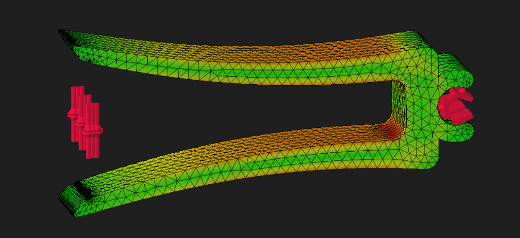
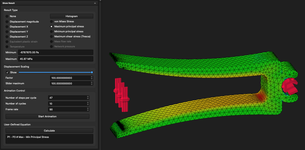
I did not expect to have such a promising first try. The picture shows the displacement when 5N are applied in each direction, so a theoretical clamping force of 10N.
In order to understand and interpret the results in any meaningful way, I read through some articles explaining the different stresses that FreeCAD calculated.
– principal stress
– von Mises Stress
– shear stress (Tresca)
– Mohr’s circle
My understanding of those articles is that for ductile materials you consider the von Mises Stress and for not ductile materials you consider the principal stress. If anyone reads this who has a better understanding of this stuff, please correct me if I’m wrong! Also… wanna hang out?
The maximum principal stress is at 45.87MPa, which is below my approximated 47MPa.
The stress is pretty concentrated at those radii, maybe I could implement a reinforcement to distribute the stress. How about enlarging the radius?
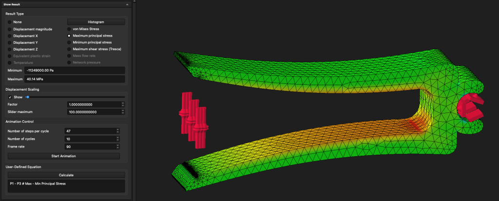
That worked like a charm! The stress is reduced by over 10%, now it’s almost 15% below my approximated yield strength. All the other stresses are even less.
I think I will end the post at this point, the next steps for this project will be printing some samples and trying to validate the simulation results. That needs to include creating an annealing and moisture conditioning process.
To be continued …
About Me
Hanna Lieding
Software/Electronics Engineer
Hello, I’m Hanni, I like to mess around with electronics, cars, drones, 3D-printers, code and broken things.
Leave a Reply